
A Comprehensive Guide (Part 1 of 2): A Review of Volatile Organic Compound Destruction Technologies
In part 1 of this 2-part series, we’re covering an overview of today’s modern VOC abatement systems. In part 2, we will share a check-list of selection criteria you can use to develop a list of detailed specifications and project requirements you can use to submit as a formal RFQ (request for quotation) to experienced VOC abatement system manufacturers.
Today’s Modern VOC Destruction Equipment Offers Multiple Choices in Technologies, Temperatures, Operating Costs & Energy Efficiency
 Environmental regulations have mandated that many businesses install VOC (Volatile Organic Compound) emission control systems since the early 1970’s. These businesses had two choices; install a VOC recovery system to destroy air pollutants or face the possibility of stiff non-compliance penalties.
While guidelines for volatile organic compound destruction are often consistent throughout various industries, your company’s desires and requirements may be very different.
When creating an optimal design for each operation, consider the following variables:
- The type and extent of air pollutant
- The temperature and volume of air exhaustion
- Expectations in future manufacturing expansion
- Geographical location
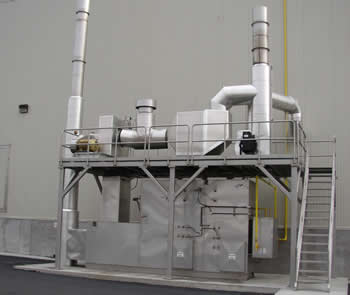
Catalytic Oxidizer Manufactured by CMM Group
Review of VOC Abatement Technologies
Thermal and catalytic oxidizers share the same basic design concept.
These oxidizers create a chemical reaction of the air pollutant with oxygen at high temperatures.
As a result of the chemical reaction, the pollutant in the air stream is destroyed and converted into carbon dioxide, heat and water. Turbulence, temperature and time are the three interdependent critical factors that control the rate of reaction.
There are two factors that distinguish one thermal oxidizer technology from another:
- The methods used to generate heat in the process.
- The temperature at which the air pollutant is destroyed.
Thermal Recuperative Oxidizer Features
Temperatures: Thermal Oxidizers operate from 760°C (1,400 F) to 815°C (1,500 F), using a tube-in-shell stainless steel heat exchanger as an air pre-heater. Oxidation occurs when the process exhaust is passed through the heat exchanger, mixed, and is held in the combustion chamber at elevated temperatures for a minimum of 0.5 seconds.
Thermal Efficiencies: In the past, older thermal oxidizer technologies achieved only 40-60% thermal efficiency and up to 95% destruction efficiency. Today, thermal oxidizer manufacturers achieve up to 80% thermal efficiency and up to 99%+ destruction efficiency with their thermal oxidizer designs.
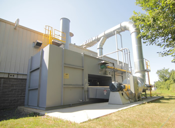
Regenerative Thermal Oxidizer (RTO) Features
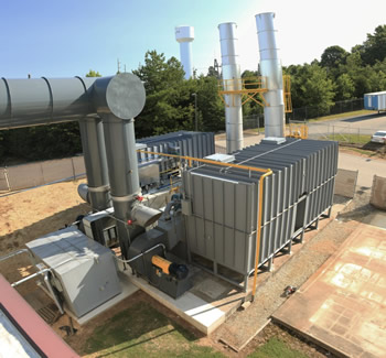
Regenerative Thermal Oxidizer – The CMM Group
Temperatures: Regenerative Thermal Oxidizers from The CMM Group are designed to destroy air pollutants emitted from process exhaust streams at temperatures ranging from 815°C (1,500 F) to 980°C (1,800 F).
The Process: How it Works
The RTO achieves destruction when the APCS supply fan directs the VOC emission into the Regenerative Thermal Oxidizer inlet manifold. The pollutant then travels through one of the two energy recovery canisters via the inlet control (switching) valves.
The air pollutant continues to travel upward from the valve assembly through the first of two heat exchanger canisters where it absorbs heat from the ceramic media. This process results in preheating the air stream and cooling the media.
At this point, the preheated air enters into the combustion compartment, often at a temperature similar to that required for thermal oxidation. If necessary, it is heated up to 1,500F and retained at this oxidation temperature for a minimum of 0.5 seconds, until it has achieved high destruction efficiency. The combustion chamber is where destruction of the VOC emission takes place. This is where, if necessary, auxiliary fuel is introduced.
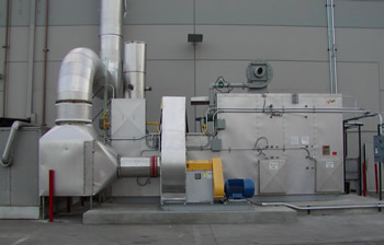
RTO (Regenerative Thermal Oxidizer) – VOC Abatement System
With the air pollutant destroyed, the clean, hot air passes back through the combustion chamber down through the second energy recovery canister. Heat from thermal oxidation is absorbed by the ceramic media and cooled while preheating the media.
The cool, clean air is then routed out to the atmosphere by way of an outlet control (switching) valve, exhaust manifold and through the exhaust stack.
The heat exchange is maximized by switching valves to alternate the airflow path between the canisters every 3 to 5 minutes. This ensures heat is continuously regenerated and stored within the ceramic media.
Thermal Efficiencies: While older Regenerative Thermal Oxidizers achieved between 80% and 90% thermal efficiency and up to 95% destruction efficiency, modern RTO’s achieve up to 97% thermal efficiency and up to 99% destruction efficiency.
Catalytic Oxidizer Features
Catalytic Oxidizer Manufactured by The CMM Group
Temperatures: Compared to thermal oxidation, Catalytic Oxidizers commonly require less energy to operate, due to lower operating temperatures. They use an industrial grade catalyst to create a chemical reaction (oxidation), ranging from 260°C (500°F) to 345°C (650°F).
To minimize operating expenses and preheat incoming exhaust fumes from the production process, Catalytic Oxidizers use a high-efficiency; counter flow plate type heat exchanger. Oxidation takes place when the emissions travel through a bed of industrial grade catalyst made of pure platinum group metals.
Thermal Efficiencies: Older Recuperative Catalytic Oxidizers reach only 50% to 70% thermal efficiency and up to 95% destruction efficiency, while modern RCO’s are designed for up to 80% thermal efficiency and up to 99% destruction efficiency.
Rotary Concentrator System Features
Rotary Concentrator Systems are hybrid VOC abatement systems designed to remove and destroy VOC emissions from a process exhaust air stream at or near ambient temperature.
This system requires a 3-step process:
Step 1) Remove the air pollutant from the air stream using a hydrophobic Zeolite rotating wheel.
Step 2) Desorb/remove the VOC/HAP from the Zeolite with a reduced air stream.
Step 3) Destroy the concentrated VOC/HAP using a RTO.
The rotor itself is made from a corrugated mineral fiber substrate, bonded with a proprietary mixture of hydrophobic zeolite and inorganic materials.
The Process: How it Works
With the ability to withstand thermal stress due to physical integrity, the rigid hydrophobic zeolite rotor is completely inert as zeolite removes VOC emissions from the manufacturing process exhaust air stream as it passes through the rotor.
Operating at an approximate speed of 2-8 revolutions per hour, the concentrator wheel continuously passes a sector of the wheel with an absorbed air pollutant through a desorbtion plenum for removal by a heated air stream. As a result, it continuously returns a clean, regenerated sector back into the main housing for further adsorption.
Desorbtion is automated as the slipstream of air that was directed through the cooling plenum is routed through a supplemental desorbtion heater were it is elevated to desorbtion temperature (typically 350°F) and sent back to the concentrator housing.
The concentrated pollutants are removed when the heated desorbtion air is sent back through the wheel via the desorbtion plenum. Finally, the highly concentrated air stream is directed to the Regenerative Thermal Oxidizer for thermal destruction.
Save Energy with Secondary Recovery Units
The latest energy saving design features are incorporated into all modern VOC control technologies, but when even greater efficiency is desired, secondary recovery units can be integrated into new oxidizer units or retrofitted into existing systems.
Older Systems are a Drain on Energy Savings
 While it is widely known that energy savings is important in new equipment, this aspect is absolutely critical when replacing older systems. If you are currently controlling emissions with a VOC system more than 7 to 10 years old, you are losing energy savings every day – and it is costing you money.
Depending on the emission control system in use, secondary recovery units capture the 250 to 1,500 degrees of heat energy that would normally be vented through the stack out into the atmosphere.
The secondary recovery unit can be designed for minimal pressure drop. This helps to avoid affecting the operation of the air pollution control system when returning temperature controlled fresh air for building heat, process make-up air (ovens/dryers, kilns, curing zones, etc.) or even replacing the need for natural gas fired burners in the manufacturing process.
Capturing Heat from the Exhaust Stream
Another way to capture heat from the exhaust stream is with a hot water or thermal oil heat transfer coil that can be installed in the exhaust stack of the system. Hot water could be returned to the process for use (condensation control, air preheat, etc.) or it can be used for heating the manufacturing plant.
The transfer coil could additionally be used as a preheat section to preheat cool water for a steam generator while thermal oil serves as a main process heat source when direct flame heating is not desired.
The heat load required from the thermal oil heating system can be reduced or even removed by adding a coil into the exhaust stream. The exhaust from the oxidizer could be diverted directly to a low-pressure steam generator, depending on the stack temperature.
If your facility uses steam, (such as through humidity control, carbon bed regeneration, etc.), while the oxidizer is running, the energy recovery system could supplement steam production capacity. Ideally, the steam from the oxidizer exhaust would enable the main steam generator to function as a back-up system.
Was our overview of VOC abatement technologies was helpful to you? Don’t miss out on the conclusion of this 2-part series,“10 Criteria You Need to Consider When Choosing the Right VOC Abatement System”

I have an industrial painting contractor here in Texas that needs to be compliant with state regulations for voc emissions. They can spray with manually operated guns up to 33.6 lbs of voc’s per hour. We are proposing a spray booth that will move 26,000 cfm. What would be a starting point of pricing for a system that could treat this volume.
Thanks
Hi
Looking for 28 gm/nm3 voc abatment system in India….Total gas flow wil be 1500 nm3\hr
Plz send your offer.
Regards
Pinesh